Interference and Diffraction
Double-Slit Interference
Two overlapping transparencies on the overhead projector are used to simulate the interference from two coherent sources.

Click the image to watch the video
- Transparencies for double-slit simulation
- Overhead projector
The double-slit interference pattern is briefly described. Two transparencies consisting of concentric circles are overlapped on the overhead projector to show the pattern of constructive interference. The pattern is observed to spread out as the two simulated slits are brought closer together. As the slits are moved apart, the pattern bunches up.
Interference Simulation Using Polarized Light
A rotating polarizing transparency on the overhead projector is used to simulate the double-slit interference pattern.

Click the image to watch the video
- Polarizing sheets for a double-slit simulator
- Polarizing sheet
- Support frame
- Overhead projector
Two polarizing sheets are prepared with adjacent concentric rings, each with slightly different polarization orientation. When one of these sheets is placed on an overhead projector with a standard polarizing sheet overlayed, the rings appear as concentric circles. As the standard polarizing sheet is rotated, wave motion is simulated. When both polarizing sheets with concentric rings are overlapped and placed on the overhead projector, the double-slit interference pattern is observed. As the standard polarizer is placed between the two sheets and rotated, wave motion from two separate coherent sources is simulated . In this manner, the double-slit interference pattern is demonstrated. The same demonstration is included in the section tiltled Polarization.
Thin Film Interference: Oil Surfaces
Oil is dropped onto a water surface and the interference pattern is observed.

Click the image to watch the video
- Abalone shell
- Oxidized copper plate
- Flat glass tray filled with water
- Puddle of water
- Oil can
Thin film interference is briefly described and demonstrated using an abalone shell and a copper plate with an oxidized surface. In an experimental demonstration, oil is dropped onto a tray of warm water and rings of color are observed as the oil spreads. A similar experiment is done on a puddle of water outside on the sidewalk. A spreading pattern is observed as the skylight reflects from the thin film of oil on the water. (Some colors may not show well on certain monitors and projectors.)
Thin Film Interference: Soap Bubbles
The thin film interference of soap bubbles is demonstrated.

Click the image to watch the video
- Bottle of liquid soap
- Ring for making bubbles
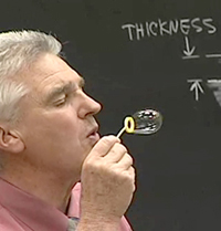
Different colors are observed to be reflected from soap bubbles as the bubbles are created. As the bubbles fall, the colors change due to a changing thickness of the soap film. (Some colors may not show as well on certain monitors or projectors.)
Interference: Hologram
A hologram is demonstrated.

Click the image to watch the video
- Hologram with lighting system
- Rotating platform
A hologram with its lighting system is briefly described and shown. The lighting system is a light bulb with a reflecting mirror. The system is mounted on a rotating platform and viewed by the recording camera. As the platform is slowly rotated, a three dimensional moving image is observed.
Single-Slit Diffraction: Laser
A single-slit together with a laser is used to demonstrate a diffraction pattern.

Click the image to watch the video
- Laser
- Variable width horizontal slit
- Variable width vertical slit
- Jack stand
- Screen
Single-slit diffraction is briefly described. As the laser beam is directed through a horizontally oriented slit, a diffraction pattern with vertical spread is observed on a distant screen. The pattern is shown to spread more as the width of the slit is narrowed and the pattern bunches up as the width of the slit is widened. The demonstration is then repeated with a vertically oriented slit, which produces a pattern with horizontal spread.
Single-Slit Diffraction: Line Filament
A single-slit together with a line filament light source is used to demonstrate a diffraction pattern.

Click the image to watch the video
- Light bulb with vertical filament
- Power supply
- Connecting wires
- Variable width vertical slit
- Jack stand
White light from a light bulb with a long vertical filament passes through a vertical slit to a recording camera. A diffraction pattern with a horizontal spread is observed for each color as the various wavelengths of light pass through the slit. Longer wavelength light is observed to spread more than the light of shorter wavelength. As the slit is narrowed, the spreading of the pattern is observed to increase. As the slit is widened, the pattern is observed to bunch up.
Diffraction: Various Objects
Various objects together with a laser are used to form diffraction patterns.

Click the image to watch the video
- Laser
- Wire mesh screen
- Piece of cloth
- Bird feather
- Diffraction grating
- CD
- Stands and clamps
- Screen
In a series of separate experiments, a laser beam passes through various objects and a diffraction pattern for each object is formed on a screen. It is demonstrated that the pattern changes with orientation of the object but remains unchanged when the object is moved vertically or horizontally. A similar demonstration is done by reflecting laser light from a CD.